Failover - Deploy Possibilities
In the previous microlearning, we discussed what needs to be done in the Design and Create phase to enable failover for systems connecting with your model. Next to that, we also discussed that setting up this failover functionality in your model requires you to execute some steps in your Design, Create, and lastly Deploy phase. Picking up from what we have toggled in the Create phase, in this microlearning, we will focus on the steps and configurations that you have to make in the Deploy phase to activate the active/passive failover functionality.
Should you have any questions, please get in touch with academy@emagiz.com.
1. Prerequisites
- Intermediate knowledge of the eMagiz platform.
2. Key concepts
This microlearning describes what configuration that you will have to do in the Deploy phase, based on what you have configured in the Design and Create phase, to enable failover for systems connecting with your model. The grouping and failover functionality is relevant when faced with maintenance and outages of systems connected to your model. The failover functionality assists in that case and allows you to have a fallback option on an active connection.
3. Deploy Phase Possibilities
3.1 Deploy Architecture
After finishing up your configuration in the Create phase, you can then move to your Deploy>Architecture. Here, you will see the new router containers, which we have seen in the Design>Architecture, to be added to your external machines. When you press "Start Editing" in this page, and then press "Apply to environment", you will be faced with a pop-up page that informs you that these router containers will be created for this specific environment.
3.2 Failover Balancing Preference
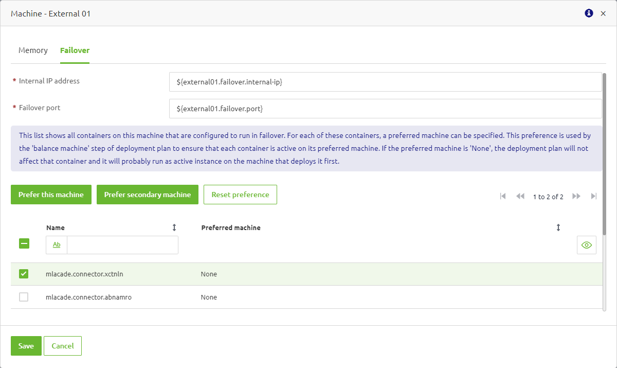
Once you have applied the changes, when you go to the "Details" of each of those machines via right-clicking them, then you can find and set for each failover runtime the preferred machine to be the leader. As an example shown in the screenshot below, there are two runtimes that are enabled for failover and you can select whether that runtime running in that "External 01" machine is the preferred leader. Another option is to set the runtime that you select as the backup, or reset it back to "None" if you want.

Notice that here you can find the "Internal IP address" and "Failover port" fields, which have been pre-filled in with property placeholders. We will comeback to these properties later in the following sections. When you have made your decision, and assuming that your machines are already deployed and running, then you can move to the other page discussed in the next section.
3.3 Deployment Plan
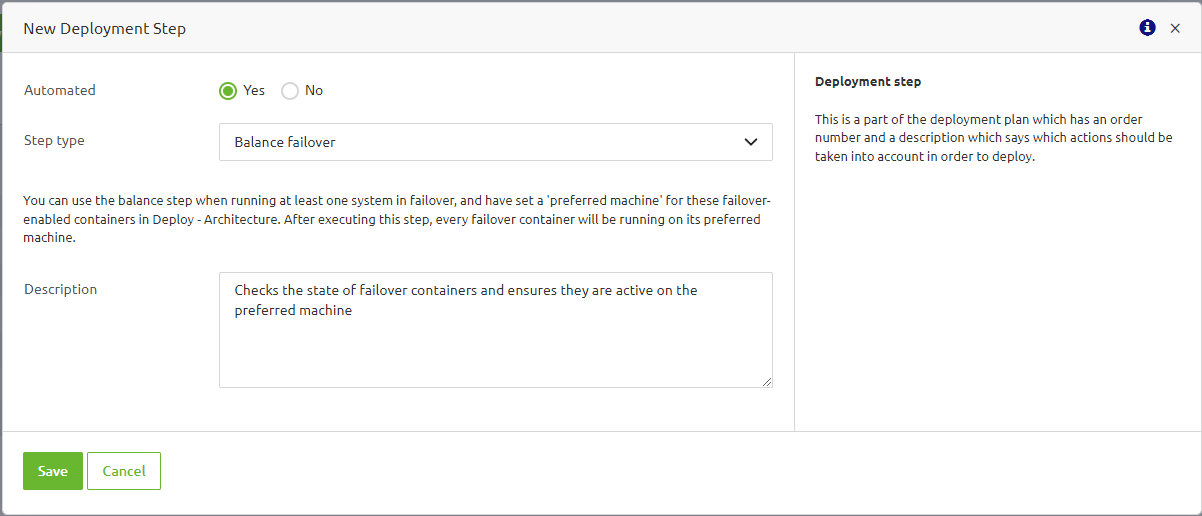
If this is the first time that you configure your failover setup, then the next step in Deploy is to check your Deployment Plan. Here, you can add a deployment step called "Balance failover", which, when executed, will trigger the failover container(s) to be running on its preferred machine as you previously configured them in Deploy>Architecture. See the screenshot below.

To make sure that this functionality works correctly, then this step should be placed at the end of your deployment plan (i.e., after the deployment of all runtimes). This is to ensure that all of the failover connector runtimes are running and reachable before electing the preferred runtime to be the leader and turning off the follower runtime. See the screenshot below as an example.

3.4 Deploy Release
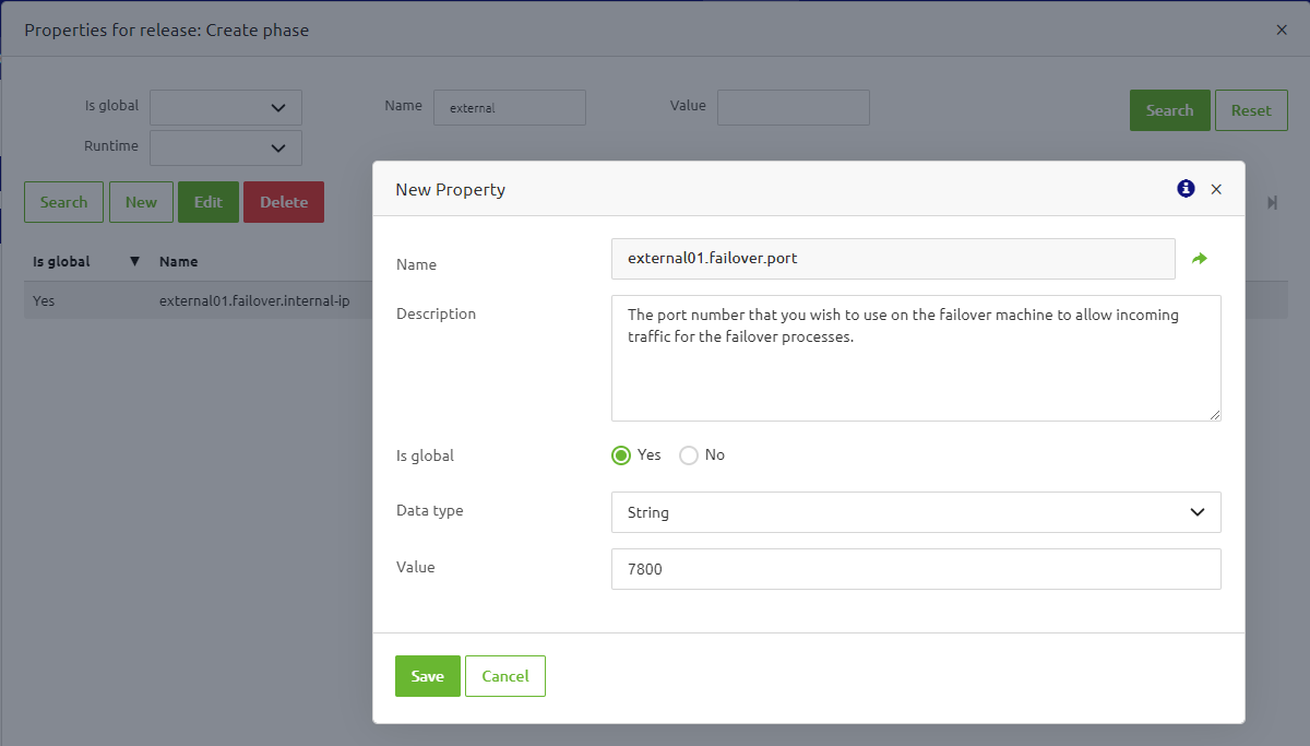
Once you have configured your Deployment Plan, then it is time to create a new release for your updated flows in the Deploy>Release page. As you might have noticed in the Deploy>Architecture earlier when opening the "Failover" tab in your machines' "Details", there are properties regarding the machines' "Internal IP address" and "Failover port". Thus, you first need to fill in these property values in the environment that you are working on at the moment (i.e., Testing, Acceptance, Production). If you are unsure on how to do this, please refer to this Property Management microlearning.
The idea here is that you fill in the IP address and the (open) port of the external machines. Thus, based on the example in the screenshot above, you can search for the keyword "external01.failover.internal-ip" and then select it. Afterward, you can set this property as global for simplicity and fill in the correct value. Once you have done so, then you can do the same for the other property (i.e., "external01.failover.port") and as well as the properties for the second machine.

When you are done, then you can save your changes, and proceed with creating a new release. For this, you will need to create a new release from your "Create phase", to include all configurations that eMagiz has provided in your now failover-enabled Create phase. Once you have done this, give the release a name and save it, then you can proceed with activating the release and deploy it.
3.5 Runtime Failover Status
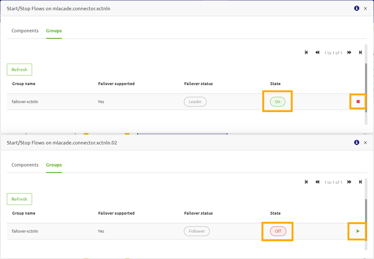
Once you have successfully deployed and run your release with the failover connector runtimes, then you can observe the follower and leadership status of your failover connector runtimes in your Deploy>Architecture. There, if you right-click your external machines (which have the failover connector runtimes) and select "Start/Stop flows", under the "Groups" tab, you will find the "Group name", "Failover status", as well as the "State" the connector runtime is in at that moment (whether it is now On or Off). See the screenshot below as an example.

The example above shows that, in that moment, the first runtime instance is currently active and acting as the Leader, while the second runtime instance that acts as the Follower is Off. You can also manually switch the leadership from one to another by clicking the Play or Stop button on the right-side.
3.5.1 Failover Status Explained
Within a failover setup, each inbound can have one of the distinct states listed below. This section explains briefly the meaning of each state.
3.5.1.1 Leader Status
If the leader status is shown, it means that this container is the Leader of this group. As a result, all inbound components with the same group name in this container are actively running.
3.5.1.2 Follower Status
The follower status is closely tied to the leader status. Inbounds with this status act as the backup. When the active Leader stops, the followers will take the Leader status. By default, the starting status of these inbounds is stopped (grey lightbulb).
3.5.1.3 Disabled Status
If the container inbounds have the status disabled, the failover is inactive. This means that the components are stopped (grey lightbulb) but will not react if the Leader stops working. To continue failover behavior, please use the steps above in Deploy -> Architecture.
3.5.1.4 Leader (single node) Status
The last possible status is Leader (single node). This means the inbound acts as a separate normal inbound with no (failover) connectivity to other containers with a similar configured group name. Suppose this status occurs in a failover setup. In that case, there is a problem in the inbounds' configuration, most likely in the cache manager or port configuration.
4. Key takeaways
- By enabling multiple runtimes across different machines, you can configure groups to operate in active/passive failover mode, ensuring continued operation during connection failures, system maintenances, or outages.
- In the Deploy>Architecture section, users can configure the router containers and set preferred machines for failover runtime leadership. This ensures that systems are prepared to handle failover scenarios.
- If users assigned the failover IP addresses and Ports properties as global properties, users must configure a "Balance failover" deployment step to trigger the failover container(s) to be running on its preferred machine as you previously configured them in Deploy>Architecture.
- After deployment, users can monitor the failover status, including leadership roles, in Deploy>Architecture, and can manually switch between active (Leader) and backup (Follower) runtimes if needed.
5. Suggested Additional Readings
If you are interested in this topic and want more information, please read the help text provided by eMagiz and check out these links:
